

INSTALLATION PROCEDURE
STEP1
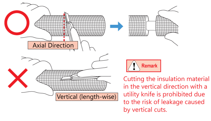
PreparationCut an insulated material
Please be careful not to damage the pipe and cut the insulation material in a cylindrical shape.
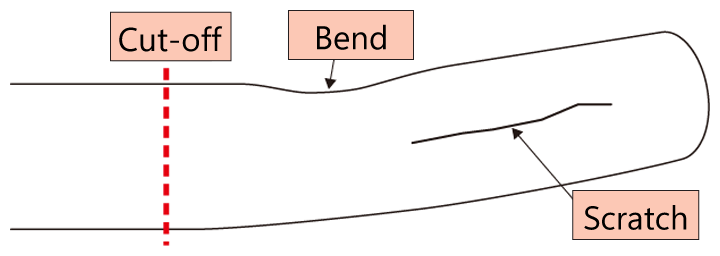
Check the pipe appearance
1. If there are scratches, bent, kinks, oval or thermal aging at the insert part, please cut it off.
2. If there are foreign materials in and outside, please remove.
■ The allowable bent and flatness of the pipe are within the range where the fitting can be inserted smoothly without any force.
■ When connecting pipes with an oxide film, please use water-resistant sandpaper with a grit of #1000 or higher to polish the pipe surface in a circumferential direction and remove the oxide film.
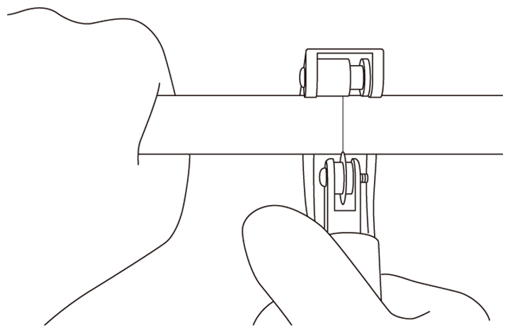
Cut the pipe
Please use a roller cutter to make a square cut.
■ Cut slowly to avoid pipe deformation
12.7mm Cutting & Chamfering of the pipe
Read more
Chamfering of copper pipe
1. Outside chamfering / Please chamfer about the half of the thickness of the pipe.
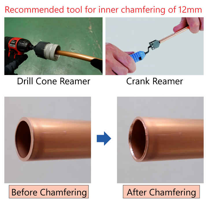
2. Inside chamfering / Remove the inner burr.
■ In case of no chamfering the outside of pipe, O-ring would be damaged and may cause the leakage.
■ Please also perform inner chamfering to ensure refrigerant flow. And also, as for 12mm, due to its built-in inner core, insufficient chamfering may lead to poor insertion and damage to the incore.
■ When chamfering, please make sure to orient the pipe end downwards to prevent any foreign matter from entering the interior of the pipe.
Let's use the electric reamer to chamfer the copper pipe to increase efficiency.
Read more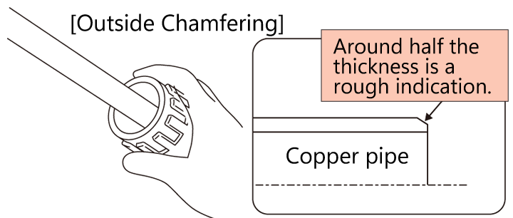
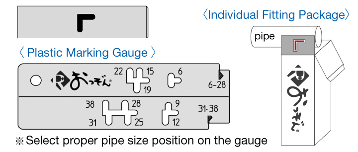
Marking
Using the side of standard line paper pattern of a fitting package or plastic marking gauge (option), mark a standard line (to fill in the designated area with T-shaped or L-shaped marks, covering the entire space within the frame.) with a marker or something like that.
STEP2
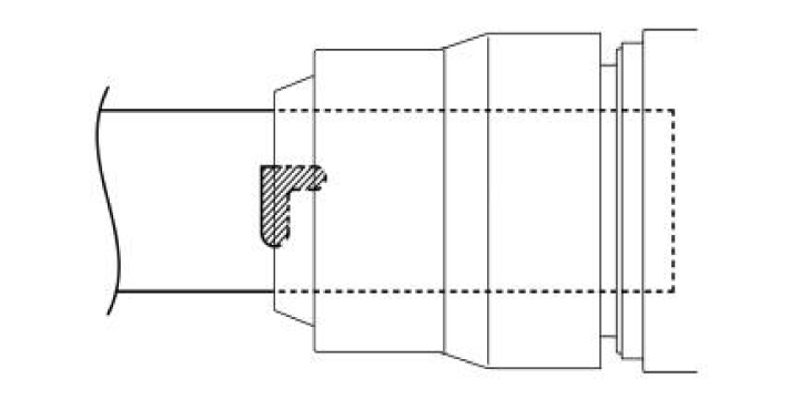
Pipe & Fitting InstallationPipe insertion
Insert the pipe until the standard line meets the end face of nut.
■ Slant insertion of pipe is forbidden to prevent the leakage due to the damage of the packing.
■ Please do not hammer them by tools during insertion.
■ Do not tighten the nut before pipe insertion.
■ Do not use the fittings which has been dropped.
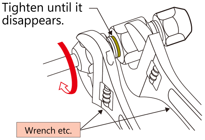
Tightening of nut
Tighten the nut by using tools such as monkey wrench into the direction of arrow until the green indicator disappears.
■ Once the green indicator is no longer visible, please stop tightening. Avoid excessive tightening, please.
■ Insufficient tightening is prohibited as it may lead to nut loosening or a decrease in fitting performance caused by the looseness of the nut. Please do not rotate the nut in the loosening direction.
CHECK
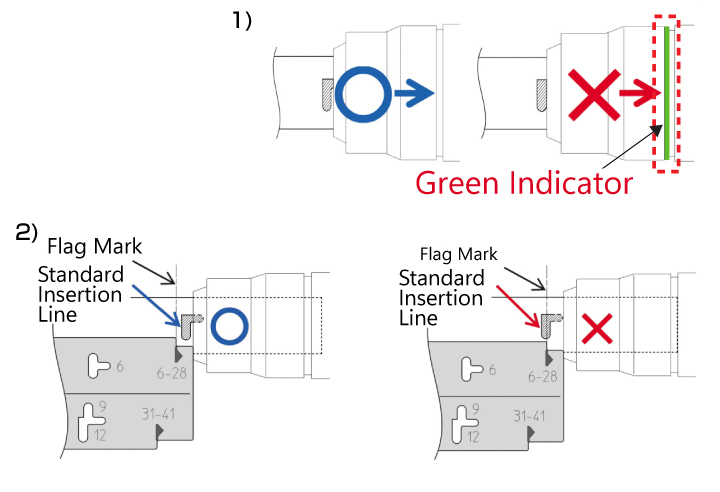
Check of the completionChecking
1) Tightening Nut → Check if Green indicator should be hidden.
2) Position of the insertion standard line → Place a marking gauge against the nut end face and ensure that the left edge of the standard line is within the flag mark on the marking gauge.
If it is not good connection, please cut the fitting and replace it with a new fitting before proceeding with the reinstallation.
Gas tightness test
Practice it according to the manual of the equipment manufactures.
Insulation
Exclusive insulation material 20mm is delivered with a each fitting package.
Even the thickness of pipe's insulated material is 10mm, to ensure security, we recommend to use this 20mm insulated material.
For elbow insulation, please use commercially available insulation materials to handle the task.
Cautions
- Do not leave the nut detached from the main body. This is to prevent foreign object adhesion and to protect the Claw Biting section.
- After tightening, do not rotate the fitting excessively.
- In case of welding near the fitting, keep a distance more than 200mm away from the fitting part and prevent the heat transfer by using a wet cloth.
- After using pipe bending tool, if there are scratches, bent, kinks, oval or thermal aging at the insert part, please cut it off.
- The sockets with nominal sizes 31 and 38 have anti-loosening rings that lock the nut when tightened, making it impossible to remove the nut. Please be aware of this.
